Commercial Modular Rig Manufacturer | OEM Gym Rigs for Sale
Most modular rig failures in commercial gyms have nothing to do with design flaws — they come from installation precision gaps and component tolerance issues.
The root cause of the majority of modular rig troubleshooting cases is bolt hole mismatches, cumulative alignment errors, and improper assembly sequencing — not steel quality or welding defects. Fixing these on-site without systematic diagnosis leads to costly rework, structural instability, and delayed gym openings.
I still remember the morning a full container of rigs arrived at a fitness chain warehouse in Chicago. The buyer had picked a supplier based on pricing and sample quality. Everything looked solid on paper. Then we opened the crates. The floor anchor bolt holes on the rig base plates did not match the American expansion anchor pattern at all. The crossbeam connector pins had visible play — a gap large enough to cause lateral wobble under load. Two upright columns were already leaning slightly from forced assembly. The gym owner was ready to reject the entire shipment. We ended up replacing the full connector kit and spending several extra days on-site recalibrating before the facility could open. That kind of modular rig troubleshooting nightmare is far more common than buyers realize. [NEED_CITE: common installation failure modes in commercial fitness equipment per ASTM F2216 guidelines]
What follows is a field-tested approach to diagnosing and correcting the issues that actually show up when modular rigs hit the gym floor.
What Are the Most Common Modular Rig Installation Failures?
The vast majority of modular rig problems trace back to three installation-stage failures: anchor bolt hole mismatches, connector pin tolerance issues, and upright verticality deviations — not material or welding defects.
When a rig arrives on-site, the first thing most installers check is whether the steel looks solid and the welds look clean. That is the wrong starting point. The real failure points are almost always dimensional. [NEED_CITE: installation-related failure distribution in commercial strength equipment per EN 20957 safety standards]
The typical failure pattern looks like this:
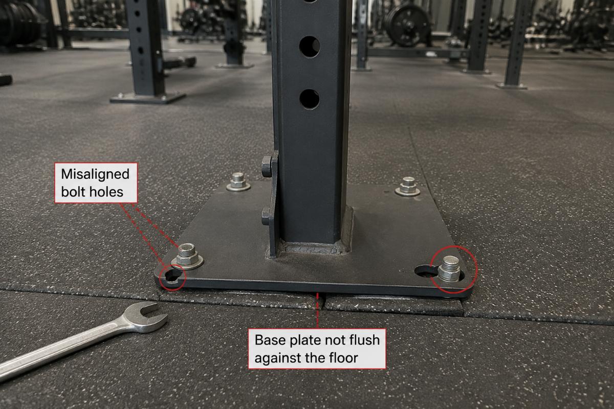
- Floor anchor bolt hole mismatch. The rig base plates were drilled to a different anchor standard than what the target market uses. American anchor patterns, European anchor patterns, and Australian anchor patterns are not interchangeable. When holes do not line up, installers either drill new holes on-site — which weakens the base plate — or force the rig into place, creating hidden stress points.
- Crossbeam connector pin play. The pins that lock horizontal beams into uprights arrive with excessive clearance. Under dynamic loading — athletes doing pull-ups, kipping movements, or heavy band work — the beam shifts laterally. Over time, this wear accelerates and the rig feels unstable.
- Upright verticality deviation. Columns lean slightly after full assembly. Most installers assume the floor is uneven. In reality, the lean is usually caused by cumulative tolerance stacking across multiple connection points, not the concrete slab.
A gym operator in the Middle East once told me his new rig felt "shaky" within weeks of opening. His installer blamed the floor. After we checked with a laser level, the floor was within tolerance. The real issue was that the connector pins had been hammered into place during assembly, creating micro-deformations that prevented full seating. The entire rig had to be partially disassembled and re-pinned. That is a modular rig troubleshooting case that started with a diagnosis error, not a product error.

How to Diagnose and Fix Bolt Hole Mismatches On-Site?
Bolt hole mismatches are resolved through adapter plates, controlled reaming, or custom anchor bolts — never through structural cutting or forced repositioning.
This is the single most frequent modular rig troubleshooting scenario I have seen across multiple continents. A container arrives, the rig goes up, and the base plate holes do not align with the floor anchors. The immediate reaction from many on-site teams is to grab a drill and open the holes. That is a mistake. Enlarging holes without proper technique compromises the load-bearing surface of the base plate and can void warranty coverage. [NEED_CITE: structural integrity requirements for fitness equipment anchoring per EN 20957-1]
The correct diagnostic and repair sequence is:
- Verify the anchor standard before installation begins. Confirm whether the facility uses American, European, or Australian expansion anchor specifications. This should be done at the procurement stage, not on installation day.
- Measure the deviation. Use a calibrated tape measure and feeler gauge to determine the offset between the base plate hole center and the floor anchor center. Document whether the mismatch is uniform across all posts or varies by location.
- Select the correction method. For minor offsets, precision reaming with a drill press — not a hand drill — is acceptable, provided the final hole diameter stays within the structural tolerance specified by the rig manufacturer. For larger offsets, use a steel adapter plate between the base plate and the floor. The adapter plate is drilled to match both the rig pattern and the floor pattern, distributing load across a wider surface.
- Avoid cutting the base plate. Cutting modifies the heat-treated zone and reduces the load capacity of the anchor point. This is a permanent structural compromise.
We now ship rigs with pre-verified anchor patterns matched to the destination market, and for markets where the standard is uncertain, we include adapter plates in the container. This eliminates the most common modular rig troubleshooting scenario before it starts. A distributor in Southeast Asia told me that after switching to pre-matched anchor configurations, his on-site installation time dropped noticeably and callback complaints virtually disappeared.

What Causes Rig Alignment Issues and How to Correct Them?
Rig alignment failures are caused by cumulative tolerance stacking during assembly — not floor flatness — and are corrected through layer-by-layer laser leveling with tight tolerance control.
Here is a misconception I encounter constantly: the rig looks crooked, so the floor must be uneven. In the majority of cases, the floor is fine. The real problem is that small tolerances at each connection point add up over the height of the rig. A fraction of a millimeter of play at each beam-to-upright joint, multiplied across multiple tiers, produces a visible lean at the top. [NEED_CITE: tolerance stacking principles in modular structural assembly per engineering installation standards]
The correction protocol is systematic:
- Establish the base plane. Before assembling anything beyond the first tier, use a laser level to confirm that all base plates sit on the same horizontal plane. Shim if necessary — but shim with hardened steel shims, not soft material that compresses under load.
- Lock the first tier completely. Tighten all connector pins and bolts on the lowest beam level before moving upward. Do not proceed to the next tier until the first tier is fully secured and verified level.
- Check verticality at each tier. Use the laser level to confirm that each upright column is plumb before adding the next beam layer. If a column is out of plumb, correct it at that tier — do not assume it will self-correct higher up. It will not.
- Control cumulative tolerance. The acceptable deviation target for a fully assembled rig should remain within a tight range measured in millimeters across the full height. If the top of a rig is visibly offset from the base, the error has already accumulated beyond acceptable limits and partial disassembly is required.
Our rigs undergo full verticality and horizontality verification at the production facility before shipping. Every upright is checked against laser references, and connector pin clearances are measured individually. This pre-shipment calibration is why our modular rig troubleshooting rate in the field is substantially lower than the industry norm. A fitness chain owner in Europe mentioned that his previous supplier’s rigs required on-site realignment on nearly every installation — with our rigs, his installation crews complete assembly without alignment correction in the vast majority of cases.

How to Prevent Structural Instability During Assembly?
Structural instability during rig assembly is prevented by following a base-first, tier-by-tier locking sequence — never by forcing components into place with impact tools.
Forcing is the enemy of structural integrity. When a connector pin does not slide in cleanly, the instinct is to grab a hammer. That impact creates stress concentrations in the weld zones around the pin receiver holes. Over time, those stress points become initiation sites for micro-cracks — cracks that are invisible to the naked eye but propagate under dynamic gym loading. [NEED_CITE: welding stress concentration and fatigue crack initiation in structural steel per AWS D1.1 guidelines]
The assembly discipline that prevents this is straightforward:
- Never force a connection. If a pin does not insert with hand pressure, stop. Check for debris in the receiver hole, verify that the upright is plumb, and confirm that the beam is at the correct height. Forcing means something is misaligned — find out what before proceeding.
- Assemble from the base upward, locking each tier fully before advancing. This prevents the accumulation of loose connections that shift during later assembly stages.
- Use only the fasteners specified by the manufacturer. Substituting lower-grade bolts or pins to save time or cost introduces unpredictable failure points.
- Inspect weld zones after assembly. Any visible deformation, discoloration, or surface irregularity near a weld adjacent to a connection point should be flagged. Critical load-bearing welds should be verified through ultrasonic or magnetic particle inspection when the rig design calls for it.
A commercial gym operator in Latin America had a rig develop a visible weld crack within months of installation. His team assumed it was a material defect. Investigation showed that during assembly, the installers had hammered several connector pins into place because the holes were slightly misaligned. The impact loading had created stress concentrations that led to fatigue cracking under normal use. That modular rig troubleshooting case was a preventable assembly error, not a manufacturing defect.

What Maintenance Protocol Extends Modular Rig Lifespan?
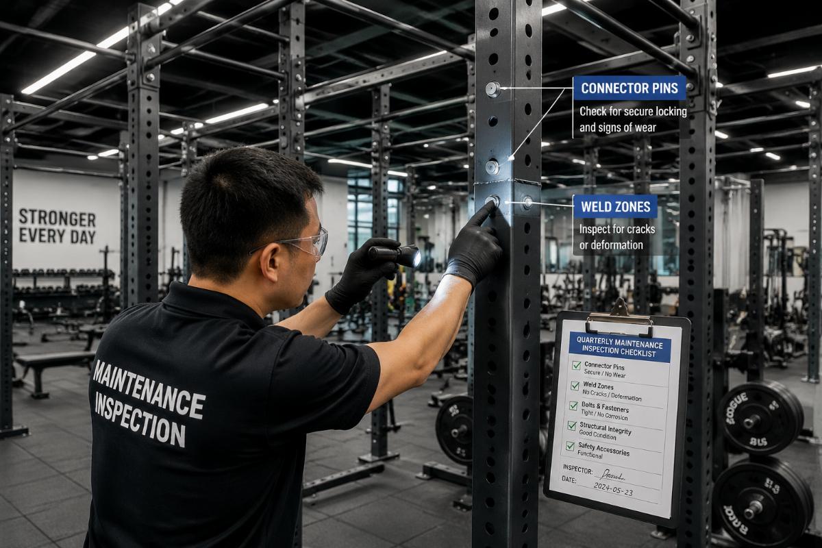
A structured quarterly maintenance protocol covering connector tightness, weld integrity, and floor anchor condition is the single most effective practice for extending modular rig service life.
Most commercial gyms operate their rigs intensively — multiple users per hour, dynamic movements, heavy loads. Without periodic maintenance, even a perfectly installed rig will develop issues over time. The maintenance protocol that matters most is simple, repeatable, and documented. [NEED_CITE: preventive maintenance requirements for commercial strength equipment per facility management best practices]
The core maintenance checklist includes:
- Connector pin and bolt tightness. Check every connection point quarterly. Vibration from repeated use gradually loosens fasteners. A torque wrench should be used to verify that all bolts meet the manufacturer’s specified torque values.
- Weld zone visual inspection. Look for any hairline cracks, surface deformation, or corrosion near welds — especially at connection points that experience the highest dynamic loads, such as pull-up bar joints and J-cup mounting points.
- Floor anchor condition. Verify that all anchor bolts remain tight and that the concrete around each anchor shows no signs of cracking or spalling. A loose anchor compromises the entire rig’s stability.
- Component wear assessment. Check connector pins for elongation or surface wear. Check beam receiver holes for ovalization. Replace any component that shows measurable wear beyond the manufacturer’s tolerance.
We provide full spare parts supply and technical support documentation with every rig order, including maintenance schedules and torque specifications. A gym chain operator in Africa told me that after implementing a documented quarterly inspection routine using our maintenance guidelines, his rigs showed no meaningful degradation in structural tightness even after extended heavy use. That kind of disciplined maintenance is what separates rigs that last from rigs that become liabilities.
Conclusion
Modular rig failures are overwhelmingly installation and maintenance issues — not product defects — and systematic troubleshooting at every stage eliminates the vast majority of field problems. Pre-verified anchor patterns, layer-by-layer laser alignment, disciplined assembly sequencing, and documented quarterly maintenance transform modular rig troubleshooting from a reactive crisis into a non-event. The rigs that perform reliably in commercial gyms are the ones where precision was protected from the factory floor through the final bolt tightening.